
|
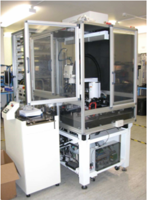
Challenge: To design and develop a revolutionary 3D measurement based Printed Circuit Board Assembly (PCBA) inspection technology to help companies improve the quality of their product. Solution: Combining the benefits of the NI Compact RIO FPGA platform and the user interface qualities of LabVIEW helped Amfax develop the world’s most accurate PCBA inspection system enabling OEM’s and CEM’s to significantly reduce their lifecycle costs. Amfax, are a global Platinum Alliance Partner of 23 years who specialize in designing and manufacturing test engineering solutions for our customers worldwide. Our extensive customer base includes blue chip companies in the aerospace, rail, transport, energy, telecommunications and consumer electronics market sectors. The challenge we have addressed by developing the a3Di PCBA inspection system is that many PCBA manufacturing companies were struggling to solve a problem of accurately and repeatedly inspecting their PCBA to ensure correct component placement and good quality solder joints to improve reliability in use.  Historically, humans have been used to visually inspect PCBA’s at the end of the production line. This is prone to poor repeatability and consistency of inspection and as such many companies have switched to Automated Optical Inspection (AOI) systems. These automated systems use cameras in place of the inspectors to capture images of the board and then subjectively compare these images against a reference standard to check if the PCBA has any faults. Any difference between the image and reference standard is flagged by the AOI as a potential failure. The local system operator must then make the final decision as to whether it is a “real” defect or not. There is always a tradeoff in these systems between generating potential failures that an operator reviews, which are known as false fails or relaxing the rules and allowing false passes. Both incur additional operating cost and can potentially affect the products quality. These systems certainly have their place as they provide significant benefits over the human inspection method and have been the system of choice for PCBA inspection for a number of years. The team at Amfax felt there must be a better, more reliable and ultimately more cost effective solution to the inherent problems associated with AOI systems, so set out to design and build the Amfax a3Di. 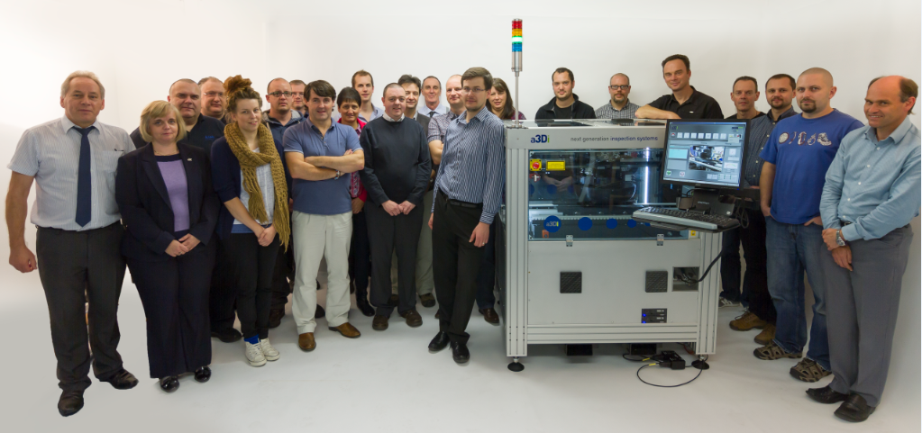 What makes a3Di unique? The Amfax a3Di system takes a completely different approach to address the challenges raised by AOI systems. It users a twin metrology based measurement technology to take millions of measurements with accuracies of under 5 microns to build a compete 3D representation of a PCBA or any other object that can fit inside the a3Di. The system scans a PCBA in a matter of a few seconds and the measurements are tested, one to one, against the original CAD dimensional data to determine whether the board has any problems relating to the component or lead location, orientation and size. Solder joints are also reviewed for shape and volume and can be matched to IPC Class 1,2 and 3 recommendations. Uniquely it measures the complete PCBA and thus can find foreign objects between packages or excessive board warpage on the PCBA that can prevent the PCBA mating with its housing at a future stage. 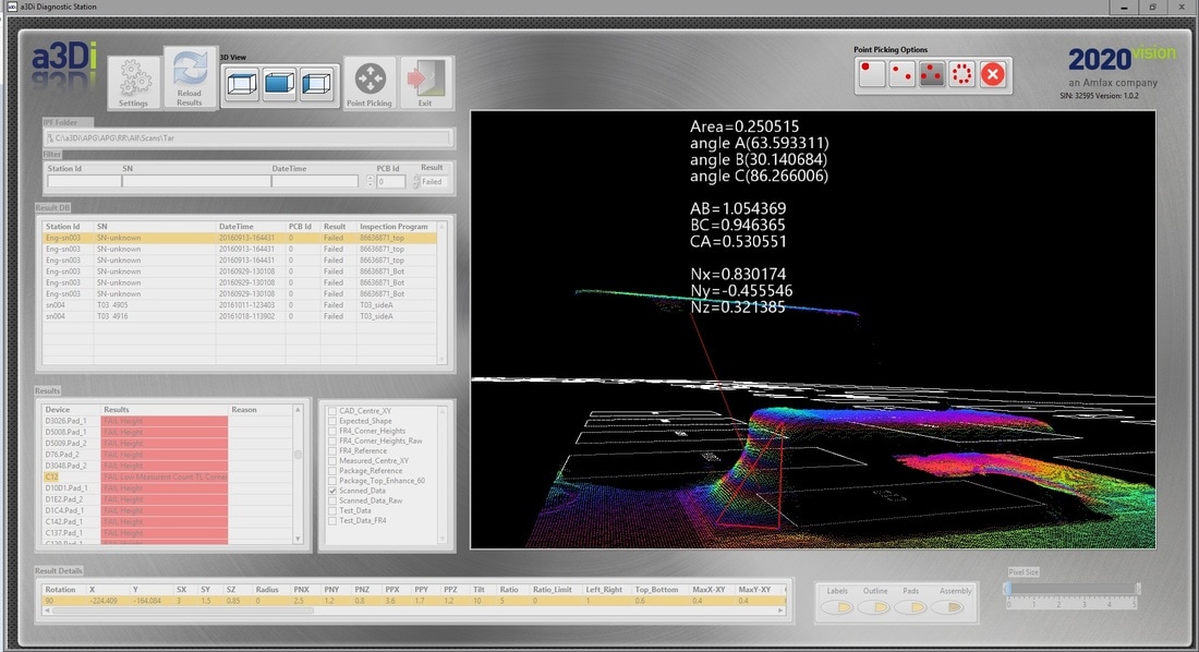 As a3Di is performing real measurement testing, there is no need for an operator as there are no false calls, either the board passes the test or not. That is the advantage of testing against real 3D measurements instead of relying on a comparative methodology such as AOI. The result is zero false calls and no subjective decisions needing to be made by an operator. This means that the users of a3Di save the cost of operators, increase product throughput and more significantly improve their product quality. NI cRIO – The heart of the machine The heart of the a3Di is the control system used to control all aspects of the machines operation. The a3Di was a brand new design for Amfax, so as a Platinum Alliance Partner our first thought was that we must use cRIO. The control system chosen for A3Di is a NI cRIO system using FPGA and the NI 9375D I/O hardware. The performance of this cRIO solution is staggering as it is controlling all of the following I/O and sensors on the a3Di. Machine motors Control switches Optical position sensors Inverters Up and Downstream SMEMA control Light Tower Pneumatics Operator manual controls for width PCB control System side EStop notifications The cRIO has proven to be a completely dependable, reliable and cost effective solution for this high performance, ground breaking application. Using cRIO as the product management system significantly reduced our development time and helped us get the various autonomous state machines of the multiple product control cells run with far tighter timings than the normal 1ms tick of most PLCs. 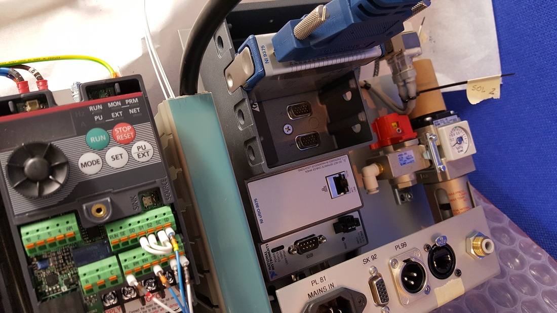 During development, our developers, who are CLD and CLA level engineers, partnered with the technical support teams in the local NI office in the UK who helped the team overcome some of the detailed control issues raised in the systems design. LabVIEW – The obvious choice for user ergonomics A decision was taken early in the a3Di product specification phase to use LabVIEW to not only provide the control code but to control the system from the user interface perspective also. The ability to design product quality operator interfaces and the flexibility of LabVIEW for creating an engaging user interface environment for the operator makes the software front end of a3Di a unique selling point. 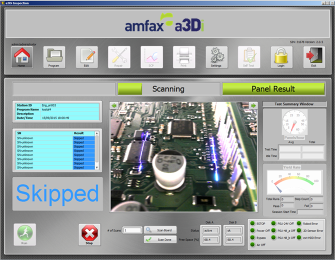 The impact of using NI components within the a3Di product enables Amfax to offer a world class, unique and well supported solution to those OEMs and CEMs looking to improve their PCBA assembly inspection process and significantly reduce their operational costs. The a3Di is also revolutionizing the way PCBA manufacturers can now compete for their customers business. By using a3Di, these manufacturers have a unique selling proposition to their own customers. They can pass on savings made by using a3Di and guarantee that the boards being manufactured are being tested by the most accurate system available to do the job. The importance of this exciting technology has not gone unnoticed, with the British Governments innovation department recognising a3Di as a significant step forward in manufacturing. The Amfax a3Di was a finalist at the 2016 Innovate UK awards hosted at the British Houses of Parliament. 
4 Comments
Requirement: To develop and manufacture an automated end of line inspection system for the fault recognition of the wire button style connectors.
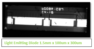
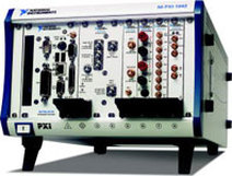
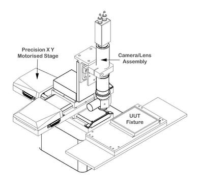 Our solution comprised of a high-resolution vision (camera/lens) system, mounted on a precision X, Y motion stage set-up. A plinth was integrated along with special to type fixtures, very accurately locates the connector to be scanned. The system was housed in a light-tight enclosure that contains a series of controlled light sources, to negate the effect of ambient light on the inspection process. A PXI controller/chassis combination provided PC based control of all aspects of the solution. Integrated motion tools allowed us to scan the vision system over the area covered by the connectors, at the very short focal length required (approx. 12mm from the connector surface). The motion system scanned a pre-determined pattern of steps in X & Y, and the vision system acquires an image at each step. The area captured by the vision system enabled testing of a minimum pattern of 16 buttons/plungers, in a 4 x 4 pattern. Further development allowed us to capture a larger image and reduce total inspection time. The image is then transferred to the vision software and processed against a pre-programmed set of pass/fail criteria, the results of which are buffered until all areas have been scanned. When complete the overall result, Pass or Fail, is displayed as a banner on the system display. System hardwareThe system was based on the PXI platform from National Instruments. A 4 slot PXI chassis houses an embedded PXI-8174 controller, PXI-1422 iMAQ vision card, PXI-7344 Motion control card and a PXI-6508 Digital I/O card for interlock monitoring etc. The software was developed using LabVIEW, the Vision and Motion modules for LabVIEW and the Motion assistant software tools, all from National Instruments. Motion/Vision System The motion system wasconstructed from two 150mm (300mm optional) precision motorised translation stages, mounted to provide travel in both X and Y for the camera/lens system. The stages had a resolution of 10um, which was more than sufficient for this application. A 20mm manual Z adjustment was also provided. The camera selected was a high resolution digital, colour model with suitable lens. System SoftwareThe software algorithm developed is split into 7 main sections. The 7 sections are as follows:
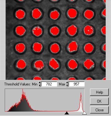
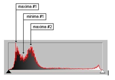
Argument sorting The function of this part of the algorithm simply extracts a 2D array from the 1D argument array being passed in by the controlling software. These arguments include which pins must be tested, and their names. Processing of half lit image This section of the algorithm takes an image of the connector lit with the red led array only. Its function is to isolate the wells on the image, and formulate an array of the wells’ coordinates and radii, which is correlated with the test array formulated in the previous section of the algorithm, ie a sorted array is passed out from this function. A general error condition is raised if the algorithm is unable to isolate a full row or a full column on the grid of wells, as this would mean that there is no reference with which to sort the array. The algorithm is capable of making multiple passes of the image to obtain a sorted array, so if the first thresholding value does not yield the correct number of wells, the algorithm will store those values it has already got, reduce the threshold value and try again up to 5 times. This image shows the ideal illumination for the image lit with the red LED array only.The illumination yields a smoothed histogram which should look like this:
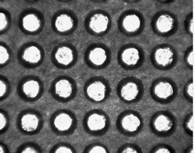
The two maxima must be clearly defined, for a valid thresholding value. This shape of graph is important because the two maxima toward the left of the graph represent the well areas and the substrate area repectively, so the algorithm will threshold somewhere to the left of the 2nd Maxima. Processing of fully lit image In this section of the algorithm, the image with both LED arrays illuminated is used. The image should look like this:
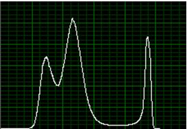
Compare the peak to the peak to the right of the histogram with the half lit histogram, this peak represents potential defect material, and has been enhanced with the second LED array. The Algorithm uses the histogram graph to obtain a new threshold value which falls to the left of the large peak to the right of the histogram graph. A particle filter is introduced also which ignores any particle below a certain threshold. This is a critical point in the code, as the value chosen for this area threshold will drastically affect the results of the tests. The default setting is 90 pixels. This section of the algorithm passes out a binary image from the above threshold / filter operations for the test part of the algorithm. Test 1 This test is for wires appearing outside of the well. A ROI is generated above the well in question using the data in the output sorted array from earlier in the algorithm and a small image extracted from the binary image generated in the fully lit image processing. Each pixel is analysed, if the pixel is high, then its distance is measured from the centre of the well. If that distance is greater than the radius of the well then a variable area is incremented. Each time this variable is incremented then the value of area is checked against a set value area threshold. As soon as area is greater than or equal to area threshold, the pin fails and the test terminates.If this condition is not met then the pin passes. The critical areas here are:
Test 2 This test uses the same binary image as the previous test, and is testing to see if there is a pin present in the well, and does this by looking for high pixels within the radius of the connector which form a single blob. The area of this single blob is measured against a constant value. If the area exceeds the value then the test passes, and fails if not. The current setting for the area is 1500 pixels. Display and report This final section of the algorithm overlays test results onto the image, and compiles a report to pass back to the calling vi. Conclusion:The system met all system requirements. The use of the LabVIEW vision and motion tools enabled a much faster and reliable test solution than the old manual test procedure. Additional software has been added to improve the feature set for the customer who is extremely pleased with the result.
Amfax also integrated an image acquisition system to provide handling with vision. This provided the system with the ability to check the device against an absolute and locate it accurately in X, Y and Theta. We were then able to check for missing devices, devices that were misallocated in their pockets and also for devices that were in the incorrect orientation.
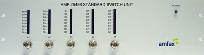
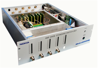
The integration of NI LabVIEW and iMAQ and control of the robot was developed by Amfax to provide a completely interactive environment specifically for handling of opto-electronic devices. The depth of field required to capture the image from the devices is restricted to 150um Temperature controlled test pedestals manufactured from elkanite, a tungsten / copper alloy were used to provide the test bed for the UUT controlled using solid state temperature sensors and Keithley controllers. To allow maintenance of the test head such as replacing Peltier heat pumps the pedestal was mounted on X and Y stages integrated into the assembly. This provided the system with fine adjustment for the UUT location and after replacement the stages could be re-taught to their zero position while not needing to re-teach the robot. The probing assembly was located above the test head and lowered into position via precision stages after the robot had placed the device. The wedge probe design from Pico probe, with kelvin probing incorporated was used for testing the chip. The typical tolerance required to make contact with each mirror was + / - 25um A single mode fibre mounted on an X / Y & Z precession stages was used to align with the wave guide of the device and measure the maximum power once voltage was applied to each mirror using the Pico probe. + / - 5um was required to maintain the sweet spot. The system was housed in a lamina flow filter system mounted on an optically flat, vibration isolated table. The chip trays were fed into the system using a mag handler operated via RS232, the system would request a product to test via an agreed RS232 string sent to the controller, the handler would then take all the steps to place the trays in a position ready for the robot to begin pick and place routine to finally test the devise on the test head Low cost, high speed 5x8 RF switch matrixThis rack mounted switch unit is designed and manufactured by Amfax. Inspired by the mobile phone manufacturing industry, this switch is designed to allow vastly reduced tooling costs for mobile phone manufacturing facilities
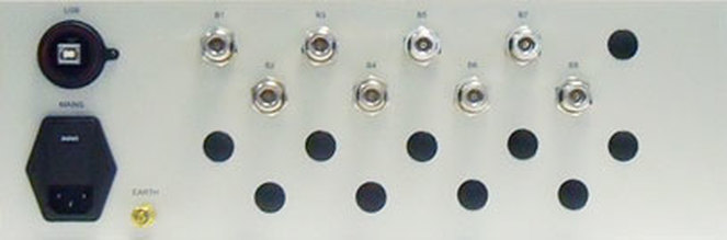
Key features and system benefitsThis Broadband Switch is a low cost, high speed 5 x 8 RF switch matrix. Benefits of this unit Reduce tooling costs Remove the need for multiple sets of test equipment Increased Longevity This switch matrix is entirely solid state, no more limited life span of electro-mechanical relays. Easy connectivity A single USB connection carries all power and comms to the switch. LabVIEW drivers supplied. RF switch specifications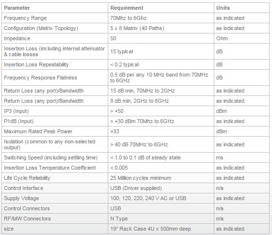 RF connectivity
 S ParametersThe following graphs show typical S parameters for a switch unit. Each unit produced is tested for all 40 possible matrix calculations, to make sure that the unit is within its specification.
Key benefits of Amfax's involvement
The resulting system was a generic test platform which allowed the end customers to strip and test Eurofighter hydraulic components without having to send them back to the manufacturer. This vastly reduced the costs for supporting operational aircraft. System safety and design innovation were keyOperator safety was a key consideration for the hydraulic test rig. Hydraulic power packs capable of delivering 360bar pressure or 180 l/m flow could do serious damage. Our solution's design addressed these concerns
System software and hardware usedLabVIEW LabVIEW was used as the primary development language for this project and delivered the following benefits :
The real time module for LabVIEW allowed us to make use of PXI RT hardware, broadening the scope and capability of this system.
Each type of hydraulic component needed its own test sequence with step by step limits and custom control conditions. TestStand was the natural choice for this and offered these benefits :
Test Bench hardware included
USER SOLUTION - Full train bluetooth auto coupler test system for Diesel Multiple Units (DMU’s)3/2/2016 As part of the general maintenance and testing of railway vehicles, the electrical systems are tested both periodically and after any repair work is completed. A key test undertaken is using the Auto-coupler Test Box which is mounted to the front of the train via a coupler adaptor. This houses the coupler plate which contains multiple fixed and sprung probes. This is connected to an operator panel using an umbilical cable fed through the cab window enabling the operator to simulate the controls of the train. Traditional Test boxes have been in service for many years and typically require replacement due to fatigue. Due to the age of the units, manufacturing information is limited and requires reverse engineering to generate schematics, PCB data and mechanical drawings. As significant cost is required to reverse engineer and manufacture the test systems it was decided to asses a more modern approach utilising ‘Blue-tooth’ technology. The solution does not require the heavy umbilical and is a more cost effective than replicating the existing hardwired solution. The design was based upon the functionality of the original design of test box. The key changes were that the umbilical will be replaced with a wireless link and the operation of the equipment will be via custom software on a laptop. This approach undertaken will allow many of the equipment constraints to be addressed including ergonomics, robustness and future expansion. Proof of conceptTo establish that using Bluetooth is a viable method Amfax conducted some preliminary tests to assess the reliability and range available. Details of the tests conducted are described below: Amfax purchased 2 modules and conducted tests within our own factory environment. The testing was completed in several steps to investigate the capability and limitations of the units. Test 1.Direct communication between the two BT Modules Two computers were used (one with each module) to establish serial communication. The distance between the computers was increased to establish the range of communication whilst ensuring direct line of sight was maintained. The connection between the two modules was then deliberately disconnected so that we could find the maximum distance at which connection can be made. This test successfully communicated over the length of our factory (50M). Test 2.Communication between BT Module and Laptop This test was similar to test 1 with the exception that one module was replaced by a Laptop with built in Bluetooth. This test was to prove that only one module would be needed in the connector box and the computer would not need any additional hardware such as a ‘dongle’. This test successfully communicated over the length of our factory (50M). Test 3.Interference communication This test was conducted twice. Firstly using the two BT modules and secondly using a BT module and a laptop. The method remained the same for both tests. One device was placed in a fixed position inside our factory building (Double layered metal cladded building). The other device was positioned outside the building. The distance was increased until there was a notable drop in speed of communication. This happened at 25M for both parts of this test and was repeated several times with consistent results. Test 4.Inside an Enclosure This test was completed to demonstrate that the BT module will operate from within a sealed metal enclosure. One of the BT modules was placed inside a 2mm thick sealed aluminum box. The laptop was then placed 15M from the box. Communication was established and worked reliably without a speed decrease. Test 3 showed that the Bluetooth can communicate over the stated distance. System softwareThe PC software was developed using National Instruments LabVIEW and the controller software developed in C++. The test software was divided into 2 sections. The first section was the main test software on the PC and the second, the software on the controller in the adaptor box. The Amfax SAM test manager on the PC was used as the base program as it allowed for easy expansion when another test procedure needs to be added. The test manager manages and runs the individual tests from one platform meaning only one program will be needed to run multiple tests, which can be added at a later date. When the test manager is activated, the user is asked for their username and password. This is to ensure that only authorised personnel can conduct any tests and also record who undertook the particular test when looking at the results. After the user has been verified the test manager opens the main menu which will have 4 options: Run Test, Reports, Settings, and Exit. Main operator screen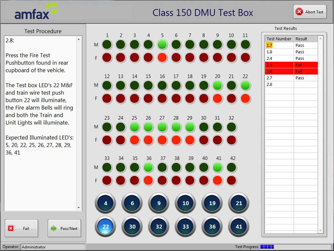 Reporting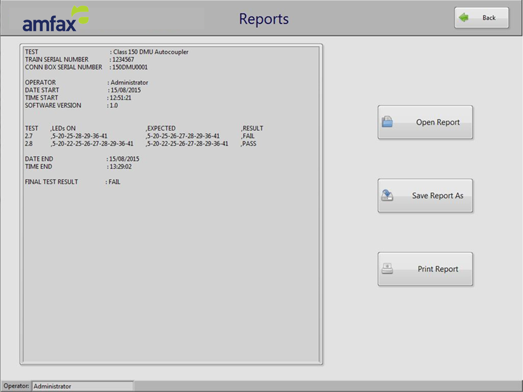 Build standardsAmfax has a proven track record for a high quality build standard which has been demonstrated in all of our projects. A senior prototype wireman was assigned as the dedicated manufacturing lead and oversaw the build process. He worked closely with the engineering team.
Internal wiring of the units was to IPC 620 standard and any PCBs assembled to IPC610. The wire type was Tri-Rated as this is high quality yet cost effective. The appropriate wire colour and gauge was pre-selected during the engineering design phase and specified using the wiring schedule. Wires and connectors were given a unique identifier using either colour coded cable idents or heat-shrinkable labels corresponding to the wiring schedule as appropriate. Consideration was given to ensure best practice techniques are applied to ensure strain relief of all cables. All metal parts were Alochromed or similar to improve anti-corrosion properties with the surfaces painted if required. All panels were electrically earth bonded to a single star point and labelled appropriately. Lock washers or nyloc nuts and were used throughout to prevent loosening of fixings and fasteners. Panel lettering were silkscreened or engraved and filled as appropriate. Each unit had an identification label containing the part number, product details and serial number. Labels were prominently placed using IEC standard symbols stating weight, lifting requirements, electrical earthing points and any hazards. All products were subject to rigorous stage inspection and final quality checks by the Inspection department before being released for final testing. During this process the units were inspected to ensure conformity to the engineering design. This included checking point to point wire continuity, mechanical assembly and fixings, correct specified components, correct wire idents, correct wire gauge and specification, crimps and connection integrity, visual inspection of labelling and earth bond testing. Inspection records were generated and stored for future reference. The portable test set purpose is to perform a simple test (go/ no go) for the the testing of Transmitter, Receiver and Code generator modules. The tests are limited to testing the primary functionality of the modules only. There are five unit types across two series types, the 2500 and the 2550, two transmitters one from each series, two receivers one from each series, and one code generator. A dedicated hardware interface is used for each module type when tested which is built into the Test Set. The Test Set includes the software to test each type, guiding the operator to perform any specific actions. The operator selects the module type to be tested and is guided to enter the correct part number through a pull down list to load the correct test set software. Only one type of unit is tested at any one time. The receiver module test requires the simulation of the transmittal tones for the test to perform correctly, where as the transmitter and code generator test requires the output signals to be analysed. 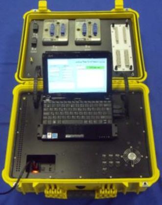 |

Our recent workWe provide regular updates on the latest projects we have been working on. Check out our archive to view all of our case studies and user solutions. Archives
April 2018
Categories
All
|


 RSS Feed