
Designing a EEPROM programmer to characterise devicesIn this case study we will show how PXI technology is used to solve a problem which requires precise timing controls, the challenges that this introduced and how we solved them. Our client's requirement was to characterise their EEPROM devices, looking specifically at how fast the devices were so that they could guarantee timing characteristics to their customers. All devices come off the same production line, but some will perform better than others. A PXI platform was ideal for this application as the PXI backplane allows for synchronisation and triggering between different PXI cards. The requirement called for I/O control of more than 30 address and data lines to the unit under test. We selected the National Instruments 6552 Digital Waveform Generator to generate programming waveforms and also read in data from the unit under test. The application required 2 such cards and so the system would have to synchronise the input/output of both cards. The timing requirements of this application were very constrained. In order to correctly chacterise a device, we had to guarantee that the required critical timings were met. Read on to find out how we solved this problem. System design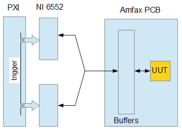 This diagram shows the major system components. The PXI chassis containing the 6552 Waveforem Generator. The output signals from this are fed into a custom designed PCB. The PCB had a 15 layers and was designed in-house by our PCB expert. The signals are all buffered and the layout of the PCB was designed such that the outputs of the buffers are as close as possible to the device under test. The final part of the track would act like an antenna so this minimises signal loss and noise. Amfax has extensive experience in programming devices using digital waveforms from both PXI equipment and FPGA Uncertaintly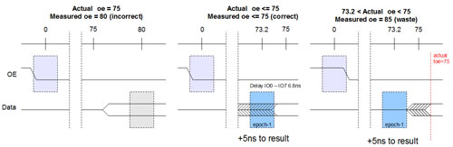 The timing between these two times has to be less than 75 nano seconds for a pass. The system had to therefore set the time to as close as possible to 75 nano seconds as possible. The PXI 6552 card has a slew of +/- 1.8ns between all of the output channels, the card is controlled via an on-board FPGA which updates the outputs every 10 ns, it is not able to update the outputs simultaneously hence the skew. The PXI 6552 card can individually delay the output of channels by one epoch/256. The timing epoch is 10ns so this gives adjustment granularity of 0.039 nano seconds. By understanding the timing diagrams, it is possible to correct this error. In the first diagram you can see what happens if you simply count 8 cycles between the events on the PXI 6552 The grey boxes show the time when a desired output may actually occur. The OE line is set at T0, but with a worst case slew this occurs 1.8ns before T0. The data becomes valid from the device at 75 ns, but the card will not read the data until 80ns. This has not guaranteed the timing requirements. In the second diagram this has been corrected. The system delays the input waveform by 6.8ns so as long as the data becomes valid before 75ns, the system will detect this correclty. As the PXI 6552 epoch is 10ns, 5ns is added to the measured time. Correcting for this skew has introduced some wastage, the final diagram shows that if the data becomes valid in the 73.2ns to 75ns region, the PXI 6552 would not be able to detect it. Re-triggering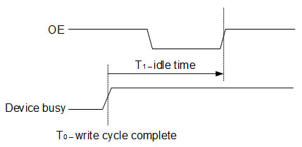 One test required checking the idle time between two write cycles. When a write cycle was completed, the device would signal it is busy and then it is ready for new input. Each device might have had a sighlty different write cycle time and so the event was considered to be asynchronous.
We made use of the powerful programming features of the PXI 6552 to overcome this problem. The PXI 6552 allows you to load up multiple waveform patterns to the card's on board memory. You can also write a pseudo-code script which includes triggering information. The Amfax PCB took the very weak output signal of the device, boosted its power through a buffer into a trigger line of the PXI 6552. The script loaded on the card was configured to wait for this signal and then output the second waveform.
1 Comment
Amfax designed and built both the test system and the fixture used for final product testing of the EBiTrack400 product range. The fixture allows the UUTs to be clamped into position and operated using pneumatically controlled automated button activators. The unit is a bespoke build utilising both custom electronics and mechanical assemblies and utilises a Virginia Panel mass interface allow control within the test system. The test system although primarily designed for use with this application was also made to be a essentially generic system allowing for modules to be added or removed as required. A fully populated unit has the capacity to contain 2 PXI chassis containing the resource to complete RF testing, vision system testing in addition to the electrical and electronic elements. The system also has the ability to be configured with a pneumatic element giving it absolute flexibility. This allows for multiple fixtures to be designed which can test a wide range of products. It also allows a system to be reproduced at minimal costs as a suitable configuration of unit can be specified to suit the needs of a particular application. To date we have completed several repeat builds and expect to continue into the future.  The portable test set purpose is to perform a simple test (go/ no go) for the the testing of Transmitter, Receiver and Code generator modules. The tests are limited to testing the primary functionality of the modules only. There are five unit types across two series types, the 2500 and the 2550, two transmitters one from each series, two receivers one from each series, and one code generator. A dedicated hardware interface is used for each module type when tested which is built into the Test Set. The Test Set includes the software to test each type, guiding the operator to perform any specific actions. The operator selects the module type to be tested and is guided to enter the correct part number through a pull down list to load the correct test set software. Only one type of unit is tested at any one time. The receiver module test requires the simulation of the transmittal tones for the test to perform correctly, where as the transmitter and code generator test requires the output signals to be analysed. 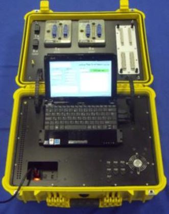 |

Our recent workWe provide regular updates on the latest projects we have been working on. Check out our archive to view all of our case studies and user solutions. Archives
April 2018
Categories
All
|
 RSS Feed